By integrating flow channels and valve assemblies, hydraulic manifolds centrally manage fluid distribution and control flow direction throughout the system, significantly improving compactness and reliability.It is important to gain a deeper understanding about their operating principles and standard symbols to make you achieve more efficient design, maintenance, and optimization of hydraulic circuits.
Next, this article will provide a detailed analysis of hydraulic manifold operating principles and common symbols.
What Is The Hydraulic Manifold?

Hydraulic manifolds are critical integrated components in hydraulic systems, designed to mount and connect various hydraulic components and piping.
They are primarily composed of hydraulic valves, hydraulic ports, and internal hydraulic passages, they centrally regulate the direction, pressure, and flow of hydraulic fluid, ensuring actuators operate precisely and reliably in coordination with system requirements.
The Primary Components of Hydraulic Manifold
2.1 Hydraulic Valves
Hydraulic valves usually use pressure-resistant materials like aluminum alloy or stainless steel, these valves are able to regulate the flow rate, pressure, and direction of hydraulic fluid according to your specifications.
2.2 Hydraulic Connectors
Connectors are responsible for linking the manifold to external piping and actuators. Common types include threaded and flanged connectors, balancing connection reliability with installation convenience.
2.3 Internal Passages
Those Includes main oil passages, relief passages, and control passages to guide hydraulic fluid flow between components, bring efficient system functionality to you.
2.4 Auxiliary Components
Beyond valves, ports, and passages, some manifolds also take designs like vent valves, drain ports, and locate pin holes to raise the safety, installation convenience, and precision.
The Working Principle of Hydraulic Manifolds

3.1 Receiving Fluid
The hydraulic power source (like hydraulic pump) draws hydraulic fluid from the reservoir and conveys it into the manifold.
3.2 Distributing Fluid
The manifold precisely distributes and regulates the hydraulic fluid and directional control valves to keep your system operating safely and efficiently through integrated control components such as relief valves, throttle valves.
3.2.1 Pressure Control
Relief valves limit the maximum system pressure and return excess fluid to the tank to avoid system overpressure.
3.2.2 Flow Control
Throttle valves precisely regulate fluid flow by altering the passage cross-sectional area, enabling you to accurately control the actuator movement speed.
3.2.3 Direction Control
Directional control valves change spool positions to open or block specific passages, which can direct fluid flow to different lines to realize flexible switching of fluid direction.
3.3. Output
Regulated hydraulic fluid is finally delivered through manifolds to actuators like cylinders or hydraulic motors, performing the action you requested.
The Function of Hydraulic Symbols

4.1 Simplifying System Representation
Hydraulic symbols replace complex components and structures with highly abstracted graphics. It makes hydraulic system schematics more concise, intuitive, and easy to understand to convince you to quickly grasp the system’s operating principles.
4.2 Realizing Standardized Communication
Symbols adhere to international standards.It means no matter where your partners’ or engineering teams are based, it is easy to recognize the hydraulic system schematic for them. This significantly reduces communication barriers and enables your projects to be more efficient throughout design, review, and delivery.
4.3 Improving Design and Analysis Efficiency
Its standardized symbol system effectively helps your engineers complete hydraulic circuit design and analysis faster, while providing clear and reliable reference for system installation, commissioning, and maintenance.
Common Symbols for Hydraulic Manifolds

Hydraulic manifolds do not have a fixed symbol shape. Instead, represented using a combination of basic graphical elements and annotations. Below you will find the most common symbols, explained in a way that helps you quickly recognize and apply them in your work.
5.1 By Symbolic Component Elements
5.1.1 Solid Lines
Solid lines indicate the primary flow path of hydraulic fluid and by following them on a schematic, you can clearly see how fluid travels through the system.
5.1.2 Dashed Lines
Dashed lines represent control lines, drain lines, or bleed lines, which can help you to distinguish different connections.
5.1.3 Arrows
Arrows are used to show the direction of fluid flow in a circuit.
When both pneumatic and hydraulic lines appear on the same drawing, you will notice that hydraulic lines are marked with black-filled arrows—this will make you quickly distinguish them from pneumatic ones at a glance.
5.1.4 Diagonal Arrows
Diagonal arrows crossing a component body generally suggest that the parameter (such as flow rate, pressure) is adjustable. And its adjustment method may be either manual or automatic adjustment.
5.1.5 Letters
Common letters are marked beside symbols to help you better differ their functions.
Common ones include P (pressure port), T (tank/return port), and A/B (working ports). With these labels, you can quickly recognize the role of each connection.
5.1.6 Toothline
The toothline can tell you this has an internal spring within a component, commonly found in relief valves, directional control valves, and other reset springs.
5.1.7 Circle
A circle represents rotary equipment, such as a hydraulic pump or motor.
5.2 By The Type
5.2.1 Outline Symbols
The outline of a manifold is typically drawn as a dashed quadrilateral (or rectangular prism). This distinguishes the manifold’s body from rigid pipes or hoses.
5.2.2 Pipe Symbols
5.2.2.1 Main Piping
The main pipeline is typically represented by a solid line, indicating the primary flow direction of the hydraulic fluid.
5.2.2.2 Control Piping
It is commonly represented by dashed lines and is used to transmit control signals.
5.2.2.3 Drain Lines
Dashed lines can also indicate drain connections.
5.2.3 Connecting Symbol

5.2.3.1 Crossed symbol
https://www.target-hydraulics.com/wp-content/uploads/2024/08/Screenshot_47.png
If pipelines are interconnected, the intersection point will take a solid circle and its diameter is typically five times the line width.
https://www.target-hydraulics.com/wp-content/uploads/2024/08/Screenshot_45.png
If pipelines simply cross without connecting, you may see them drawn as straight intersecting lines or as one line “jumping over” the other.
5.2.4 Port Symbols
Ports are shown as small squares or circles. They represent the connection points between the manifold and external piping or components, which can make you quickly locate interfaces in a schematic.
5.2.5 Hydraulic Valve Symbols
Hydraulic valve symbols are generally classified by function into three types: directional control, flow control, and pressure regulation.
5.2.5.1 directional control
5.2.5.1.1Hydraulic Check Valve
https://www.fastercouplings.com/files/uploads/check%20valves%20symbols.jpg
A hydraulic check valve’s sign is a circle with an arrow inside pointing in a single direction that means it only allows fluid flow in one direction. You may see a control signal port alongside the symbol at some time, signifying that the valve requires a control signal to operate.
5.2.5.1.2 Hydraulic directional control valve
https://www.e4training.com/hyd_princip/picts/symbols/direct3way.jpg
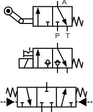
The directional control valve’s symbol consists of a square frame, an arrow, and letters. The number of boxes shows how many flow paths the valve can switch between, while the arrow indicates which oil line is in the open position. Common letters, such as L denote this is a drain port.
There are many types of directional control valves such as two-position two-way valves and three-position four-way valves.
5.2.5.2.Flow control

5.2.5.2.1Throttle Valve
The symbols of throttle valve typically feature diagonal arrows or wavy lines, with the arrow direction perpendicular to the fluid flow direction, indicating that flow rate can be adjusted.
5.2.5.2.2 Speed Control Valve
It is composed of two adjacent boxes. The left box represents a flow control valve, while the right box contains a vertical solid line and a dashed feedback line, indicating it is able to reduce pressure and regulate flow.
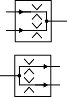
5.2.5.2.3 Diverter valve
The symbol for a hydraulic diverter valve has multiple branching arrows within a square frame, telling that hydraulic fluid is distributed to different circuits.
If it requires proportional flow division, you will see the proportional value labeled next to the arrows.
5.2.5.2.4 Manifold valve
https://www.e4training.com/hyd_princip/picts/symbols/flow-divider.jpg(第一个是)
In contrast to a hydraulic diverter valve, the symbol consists of many arrows converging into one, meaning that multiple fluid inlets converge into a single outlet.
5.2.5.3 Pressure Regulation

5.2.5.3.1 Relief valve
The symbol of the hydraulic relief valve features an arrow pointing from the inlet port to the relief port, indicating that hydraulic fluid will be released when the pressure exceeds the set value.
If you see a small box connected to the symbol by a dashed line, it signifies that this is a pilot operated relief valve.
5.2.5.3.2 Pressure Reducing Valve
The sign of a hydraulic pressure reducing valve is drawn with rectangles, arrows, dashed lines, and solid lines.
The arrow shows the flow direction from a high-pressure port to a low-pressure port, while the dashed line section represents the feedback loop returning from the outlet to the valve spool.
5.2.5.3.3 Sequence valve
Arrows, solid lines, and dashed lines are used to draw the hydraulic sequencing valves and its function sequentially executes actions based on pressure changes.
Solid lines represent internal connections between the inlet and valve core, while dashed lines denote connections between external control ports and the valve core.
Conclusion

Hydraulic manifolds can integrate multiple valves and lines and make your hydraulic system to achieve efficient, precise, and reliable control within compact spaces. Understanding how hydraulic manifolds work and mastering standardized hydraulic symbols allows you to quickly grasp system principles and facilitates efficient communication with global engineering teams, shortening design cycles and reducing maintenance costs at the same time.
If you have any questions about hydraulic manifold principles or symbols, feel free to contact us anytime.